I thought it would be a good article to review a hub overhaul on a nice set of Mavic wheels before your spring riding season heats up (at least on the East coast). Mavic wheels are quite popular today and the first important thing to remember is that with only minor variation, most Mavic hubs are built similarly and can use the same freehub body on any of their wheels (Occasionally an older freehub will need a sleeve included with new freehub bodies today, but otherwise is the same). These wheels have a simple yet elegant design that holds up under a variety of riding conditions, is tubeless and 11 speed compatible, and resists corrosion and wear exceptionally well. The Ksyrium (pronounced “Seerium”) is Mavic’s most prominent wheel and is competitive in both weight and ride quality to most other major wheel manufacturers.
However, despite all of these great points, the hubs still need servicing to remain in top shape and performance and doing so will greatly extend the life of the wheel. A lack of maintenance can lead to a slower wheel, and when coasting, a high pitched squeal. This is indication that the inside of the freehub body is dry as well as the rubber seal the freehub sits on. Dirt and water can still invade the bearings even though they are “sealed” and the dirt can cause wear on an otherwise forever-lasting freehub body. Most of the wheels that need the freehub body actually replaced are due to a lack of scheduled maintenance rather than it simply wear out due to riding alone. Let’s dig in!
The front hub is really easy. it requires the Mavic tire lever and a 5mm hex key. On the end of the tire lever is a U-shaped curve with two pins on each side. These pins fit exactly into the holes on the non-drive side of the front hub. the 5mm hex key is inserted into the opposite side of the hub through the axle. Loosen the axle with the 5mm hex key (CCW) while holding the tire lever in the preload cap with the pins. When reassembling, we will discuss its purpose. Once the preload cap is off of the hub the axle can be pulled out through the side with the hex key. Inspect the bearings on each side as seen below.

 You’ll likely notice a bit of grease and dirt on the bearing seals. With a bit of isopropyl alcohol, clean the hub area around the bearings and then rotate the bearings to check for gritty spots or rough turning. You should feel continuously smooth rolling with no drag points if the bearings are in good shape. If they do need replacement, they can be ordered from your local shop and easily installed with a small bearing puller and bearing press. This article doesn’t cover the actual replacement of the bearings, but a video is being planned to detail appropriate bearing removal and installation.
Continuing on, if the bearings are in good shape, use isopropyl alcohol to wipe down and clean the preload cap and the axle. be sure to pop the end of the axle off that are fitted by compression using o-rings. It is a great idea to apply a small amount of light grease to these so that they will not creak or be difficult to remove for cleaning. Inspect the o-rings for cuts or abrasions and replace as necessary.
 This is the axle and corresponding cap and end cap for each side. Note that the large circular caps have one with the preload pin holes and one does not. The one that does not just slides onto the axle until it hits the lip on the right side of the axle in the photo above. The preload cap with the pin holes threads onto the axle after inserting it through the hub. be sure to grease the axle before so it installs easily. Using a 5mm hex key and the preload end of the Mavic tire lever, thread the cap on the axle until it starts to tighten up. Then, back the preload cap off bit by bit will wiggling the axle to detect any play. As soon as the play is gone, stop. The hub now will spin as freely as possible without having bearing play.
Now, onto the rear hub! The rear is a little more complex, but works on the same principles as the front for most of the axle assembly. The rear hub also has the 5mm hex key opening on the drive side of the axle. On the non-drive side the end cap can be pulled off with your hand. It is fitted onto the axle with a compression o-ring, much like the smaller end caps on the front hub. This is where greasing the o-ring will help greatly. If the o-ring is dry, it may be difficult to pull off. In that case I take a cone wrench slightly bigger than the cap and use it to pry the cap off. Also, an axle vise works great in this case. Drip a couple drops of Triflow on the cap so that the o-ring is lubricated. Once removed, look at the inside of the hub. You’ll see flats for a 12mm hex key. Insert a 12mm hex key into the non-drive side and a 5mm hex key into the drive side and turn each CCW. Reference the photo below.
 Above is the removal of the axle and the non-drive side end cap removed from the axle. The non-drive side of the axle will stay installed in the hub for the moment and you’ll notice the drive side of the axle threading itself out of the axle. Once unthreaded, pull the drive side axle out and set to the side. Then, carefully pull the freehub body off of the hub. It usually does not take much pressure. However, two pawls and springs that cause the ratcheting mechanism of the freehub body to work are right under the freehub on the hub shell itself and can spring right off into space if you aren’t careful. If the springs somehow are lost, don’t even both searching for them unless you don’t have new spare ones. You will literally never find them until your next shop winter cleaning. Maybe not even then. I have searched and searched for these things and generally come up empty-handed. I mention this in such importance because it is easy to lose these springs. For that reason, if you are a shop, buy spare parts for these wheels. They can be used in all Mavic hubs and are cheaper than the time you’ll waste looking for the old ones. If you are a home mechanic, buy some too, but put the springs upon removal from the hub directly into a magnetic parts bowl. They will stay put and can even be cleaned easily in the bowl. This is what the removal of the freehub body looks like.

 The top photo is of the hub shell under the freehub body and the bottom photo is of the freehub body inside and the drive side axle end. Notice the dirt, grime, and dirty grease present on the white/tan bushing on the inside of the freehub body. This bushing is identically machined to each Mavic wheel hub shell when they are made, which creates an amazingly amooth and wear free part. The killer to the eternal lifespan though is allowing this bushing, the inside of the freehub body, and the pawls and springs to get dry and/or dirty. Using isopropyl alcohol, clean each part thoroughly and inspect the bearing in the freehub body from wear. This bearing is a #608 and another is on the outside of the drive side hub shell as seen in the top photo. The non-drive bearing is a #6903. Here is a photo of the pawls and springs removed for inspection and cleaning.
 The left pawl is showing the outside edge. Once cleaned, inspect this edge. If there is a shiny wear mark , it is time to replace them. If the coloring of the pawl is even almost out to the edge, they should be okay.
 Once you have removed the pawls and springs, use needle nose pliers and gently pull the freehub body seal off of the hub shell. When this is not properly lubricated, that is what causes the high-pitched squeal when coasting down hills. It also keeps the mineral oil we will use for the freehub body to stay inside the freehub — allowing better lifespan and performance. Clean the hub shell as well.
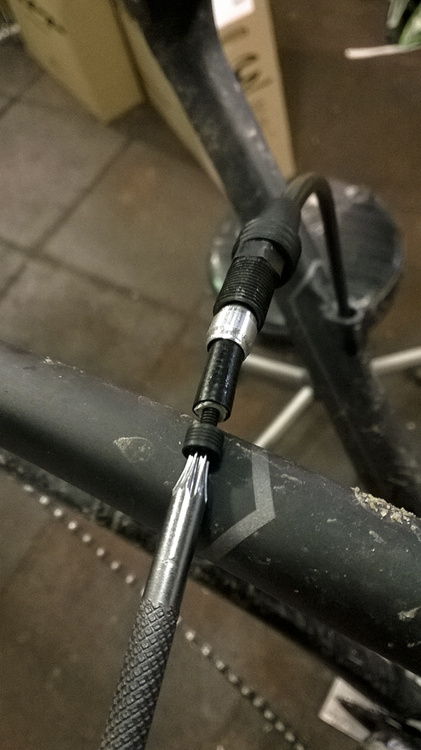
Using the 12mm hex key and the Mavic tire lever, insert the 12mm into the non-drive side of the axle and insert the preload adjustment into the preload cap. Unthread the preload cap and pull the axle out of the hub shell.
 Inspect this bearing as well and clean the axle and preload cap with isopropyl alcohol. Be sure to add grease to the preload cap threads when reinstalling for smooth adjustment.
 Once everything is cleaned and inspected, it’s time to reassemble the hub. Insert the axle with a small amount of grease through the non-drive side of the hub shell and thread the preload cap on just a couple turns. We will come back later to adjust it. Tightening it down now will cause the bearings to bind when the drive side of the axle is installed and tightened.

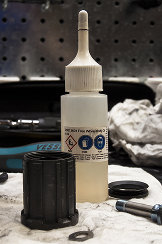 Drip about five drops of mineral oil (15wt) from Mavic into the freehub body and set on its side so it doesn’t drain out. Then, apply a bit of mineral oil to the washer between the freehub body and hub shell, seen at the bottom of the above photo and also again slightly set to the side in the photo below.
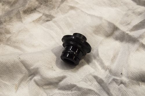
 If this washer is not installed, the axle and bearings will bind terribly. It spaces the freehub away from the hub shell properly so the compression of the freehub seal is not too tight.
 Next, install the rubber freehub seal and the pawls and springs. The springs fit over a pin on each pawls and then into a corresponding hole on the hub shell where they sit. I usually drip a drop of mineral oil on these two and press them a few times to make sure they spring back open properly and smoothly. Once these pieces are installed, slide the freehub body onto the hub shell. When it hits the open pawls, use two fingers to depress the pawls and continue sliding the freehub body on. Once fully seated, insert the drive side axle with a bit of grease or light loctite and thread into the non-drive side axle until tight (about 8-10Nm). Turn the freehub body and listen for the correct and constant ratcheting of the pawls.
 Flip the wheel to the non-drive side and using a 12mm hex key and preload adjustment lever, tighten the cap down as mentioned in the front hub overhaul procedure and back it off until any play in the axle is gone. That’s pretty much it. Other than cleaning the rest of the wheel and truing it, the hub overhaul is complete and your wheels will be ready for another season of riding. I am convinced that if you do this with your wheels before and after winter, you’ll keep your Mavics running for years and years without trouble. As always, feel free to comment or send questions.
In the next few weeks, I am attempting to film some short repair videos and have had a request for one for the Dura-Ace 9000 front derailleur setup. This will be the first one with clips on the variations in setup for the Ultegra and 105 level components.
– SNC