I thought I would write a review of how to install and adjust / bleed the newest road hydraulic disc components from SRAM (the SB700 series). They just arrived at the shop a few days ago and I was anxious to see what the differences were and how they would perform once installed. As normal, there were some easier parts and more difficult ones and I am sure I will encounter new challenges with it for each new frame it’s installed on.
This review is based off of a popular frame — the Specialized SWORKS Crux. It’s cable routing was designed to use road hydraulic brakes (or mechanical) and was the first one in the shop to be updated. Here goes.
This is the group right out of the package. This is the SB700 series and it also came with Zipp Service Course SL tape (black), new rotors/pads, and caliper bleed blocks.


The front and rear setups were in separate boxes and packaged well. The only thing that I would have liked to have seen would be a printed copy of the bleed procedure. However, I did find it easily online here
This bike stayed in the shop from the initial recall and so removal of the recalled hydraulic brakes was fairly quick and easy. I cut the lines for the rear brake because of the internal routing and pulled the line through after installing this little connector and hose plug to avoid DOT fluid dripping through the frame.
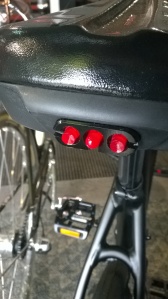
The first thing I did was to clean all of the surfaces the components would be installed to with isopropyl alcohol. This leaves no residue and provides the cleanest contact surface. Before this, I also disconnected and removed the old derailleur cables. Installation of the brake/shift lever is next and was mounted using a small amount of grip paste behind the handlebar mounting bracket to ensure stable placement and zero movement while riding. Photos below.


Once the lever was installed, I checked out the caliper to notice any differences. These next photos are of the caliper installed and on the bench. I figure it is more useful to know as many things as possible before the install and some of these things were discovered throughout the installation.


In the above photos, you will notice that the caliper looks about like any other hydraulic caliper out there with a few minor differences. First, the hose can be cut and sized for the frame at the banjo. Where older style brakes seemed to always have the crimped metal cap on the hose where it meets the banjo on the caliper, there is a standard 8mm fitting bolt that compresses an olive and barb into the body of the banjo. Secondly, the pads are uniquely shaped compared to other SRAM/Avid brakes. Lastly, the safety retainer clip for the bolt that hold the brake pads in the caliper is clipped on the inside of the body, where the edge of the pick is pointing in the second photo. As a side note, I just realized the potential to use the bleed block as a tool to hold the hose while installing a barb by squeezing the end of the bleed block that is slotted.
Next, the front caliper was installed and appropriate measuring for the hose was fitted for the frame. I used the smaller cylindrical caliper mounting spacers and found it to look sleek and minimal while providing a stable “post” for the caliper to mount to.


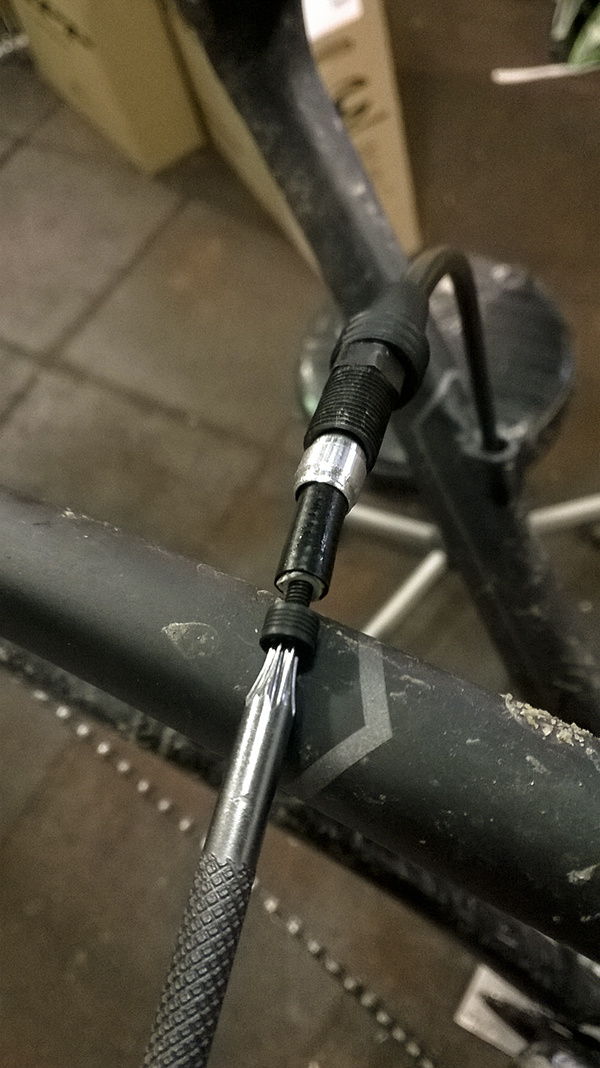
Cutting and sizing the hose for the front brake was relatively easy and required about the same time as it does for a mountain hydraulic brake. With no internal routing for the front brake, it simply passes in a nice arc in front of the head tube and follows by a retainer clip on the fork down to the caliper. Pivot washers and new mounting hardware were all included (a 12mm top spacer and a 7.5mm bottom spacer for a 140mm rotor)(A standard adaptor was also included for a larger rotor).
Now, I’ll cover the installation for the rear brake and then go over the bleed procedure last. The rear brake hose, as mentioned earlier, is routed through the frame, below the bottom bracket to the non-drive side of the bottom bracket cable guides for the derailleur cables, and out of the rear non-drive chain stay to the caliper. The caliper mounts directly to the frame mounts along with pivot washers.
One of the important factors in internal routing for hydraulic hoses (and full-length housing) is being able to wrap cushioning around it to prevent rattling in the frame every time the bike hits a bump. Specialized had provided a spiral foam insulator that was wrapped on the excess of the hose and pushed into the frame where it passed below the bottom bracket (shown below)

The bottom of the photo is where the insulator is pushed into the down tube. It is incredibly helpful to use some sort of snaking light to illuminate the inside of the frame so the derailleur cables can be checked for crossing when installed (also internally routed). It’s an easy thing to miss with all of the other focus points of the install and will definitely lead to terrible shifting. I left the hose for the install as long as possible (cutting it about two inches from the banjo on the brake caliper) so there would be plenty to use for correctly sizing to the frame. I would note that gloves are definitely useful and necessary while routing the cable so no DOT fluid contacts the skin.


The routing through the frame wasn’t as difficult as I thought it would be since the hose was fairly rigid and could be easily seen with the light shown into the frame. Using the little red plug also marginally helped to prevent lots of air from entering the system while installing, which made bleeding the brake quicker and more effective afterward.
The pads lined up to the rotors well for the front and rear. The pad spacers were held in place well and resisted falling out (great for packing and transporting). Before bleeding both brakes, I went ahead and installed the derailleur cables back onto the components and adjusted as necessary.
Once the rotors, levers, shifter cables, hydraulic hoses, and calipers were all installed, it was definitely evident and expected that one or two bleeds would be required to get the correct actuation of the lever. Initial pulls on the lever yielded solid piston movement in the caliper — even with air in the system.
The bleed procedure is quite normal and easy. The bleed port on the lever is located at the topmost section of the grip, underneath the rubber. A standard T10 fitting right in the center connected to a 1/4th filled bleed syringe with DOT 5.1 fluid and a hose clamp. The inner part of the caliper body bolt is the second fitting (also T10) for the 1/2 filled syringe of DOT 5.1 fluid with a hose clamp. Past this, the bleed procedure is described in depth, step by step at the link mentioned at the start of the article.


A few things to remember — clean the entire caliper with isopropyl alcohol after bleeding the brake and before reinstalling the brake pads. Use the included bleed block. Do not forget the clip for the retainer bolt on the caliper that holds the pads in place. While not critical for the brake to function, it is a safety clip so the pads do not vibrate out and cause the pistons to contact the rotor in the event of a failure. Lastly, always go through the bleed procedure step by step. As noted in the manual, it may be necessary to bleed the brake more than once for the initial install. I bled the rear brake twice and the front brake once (due to less air exposure than the rear and great results after the first bleed).
I checked the position of the brake pads in relation to the rotor and centered them on either side by loosening and tightening the mounting bolts and placing a white sheet of paper below the caliper (which makes it incredibly easy to see the space between each brake pad and its respective side of the disc rotor). Once fine-tuned, I test rode it around the area outside our shop and was noticeably impressed.
The shifting performance felt better than the original hydraulic version and slightly better than the mechanical 22 groups. The brake pads were burnished to the rotors with about 40-50 hard stops and responded quickly to fast braking and slower modulation. The reach can also be adjusted for quicker pad contact and shorter distance to the handlebars.
All in all, I thought the install took an appropriate amount of time and was well prepared for by SRAM. The bleed procedure is quite like their mountain brakes, which is easy and was convenient to perform with a brand new bleed kit included with each set of brakes. The braking power was solid and adequate. I’ll be awaiting real ride feedback from riders picking them up as I finish installing the others.
Please let me know if you have any questions or comments regarding this article or in your own install as I am always looking to expand the knowledge base to provide accurate instructions and review. Thanks for the support!
– S.N.C.
As a final note, we also just got a shipment of the new Pinarello Dogma F8 — an incredibly light frame with post hardware rolling in at about 980g! Below are photos of the frame before the build and I’ll have build photos in the next week as five are already getting ready to head out to the road for takeoff!
This slideshow requires JavaScript.
 Before you place this washer onto the anchor bolt, apply a small amount of grip assembly paste to the surface at the base of the anchor bolt, as shown below.