Installing and Troubleshooting the Turbo S Wiring Harness

It’s been a little time since I had a good update of info and experience with working on the Specialized Turbo S (in this case, the first gen version) and have had notable experiences that deserve to be logged and written about.  So, here goes.

In my last post, I was working with a Turbo S that had error code LEDs for the 1st, third, and fourth on the battery and would subsequently turn off after about five seconds of turning it on.  I have been working constantly with Specialized on this one and the valuable experience I have gained will be explained below.  In the end of my discussions with the Turbo experts at Specialized, it was determined that the wiring harness was malfunctioning and needed to be replaced.  It was estimated at about a two hour job, uninterrupted and I think that accurately reflects the time it takes for someone familiar with the Turbo.  Below, I will run through the process and how to do it with advice on what to avoid doing or what helps the install go more smoothly.  As of now, this is the first coverage I can find anywhere on the Internet on how to do this, so I hope the documentation is thorough and helpful.

After swapping several of the components with new ones from a known working 2013 Turbo S, I encountered the same errors on a consistent basis (even with two other batteries).  When the wiring harness came last week, I was psyched and ready to dive in.  I took photos of the whole process so you can visually compare when working on this project yourself.

The first part of the project involves removing the old wiring harness first.  This is literally every wire that runs from the handlebar connectors (the brake motor disengage, the mode selector, and the control interface) to the back of the bike.  First, remove the small 2.5mm hex bolts that attach the frame stops/guides for the wires on both side of the frame where the downtube meets the headtube.

WP_20151015_13_37_37_Pro WP_20151015_13_37_47_Pro WP_20151015_13_37_52_Pro WP_20151015_13_38_03_Pro WP_20151015_13_47_33_Pro WP_20151015_13_47_42_ProWP_20151015_14_53_36_Pro

Once this is done (by the way, put these tiny screws in a magnetic parts bowl, because you WILL LOSE THEM OTHERWISE), remove the anchor bolt on the non-drive side of the bike (which holds the main part of the wire harness in place).  It is a 6mm bolt that uses blue loctite.  In addition, this is a great time to replace the rear derailleur cable as the housing where it fits into the rear derailleur housing stop usually is bent and stretched.  Clip the housing on each end clean.  Any exposed housing casing will cause friction in the cable and affect shifting.  In the fourth photo, you will see a tiny 2mm screw right in front of the wire harness in the battery compartment.  You MUST remove this screw (which holds the brake housing securely under the downtube).  More photos below and then the next step.

WP_20151015_17_25_10_Pro WP_20151015_17_25_01_Pro WP_20151015_13_50_49_Pro WP_20151015_13_51_35_Pro WP_20151015_13_57_36_Pro WP_20151015_13_57_44_Pro WP_20151015_13_57_52_Pro WP_20151015_14_00_17_Pro WP_20151015_14_01_19_Pro

When doing this project, I suggest removal of the crank.  While the bottom bracket isn’t necessary to remove, uninstalling the crank is a good idea so you have better angles of working with the bottom bracket access point on the frame.  It’ll make your life a whole lot easier.  I also discovered that you only need to loosen the two hex bolts (5mm) inside the bottom bracket access point in order to successfully route the harness.  Each individual wire (3 of them, black, red, and orange) is easiest to pass through the routing individually.  When pulling the wiring harness center out of the frame, it’s a good idea to take a nice flat tip screwdriver and carefully pry the rubber casing on the harness wires going down the battery compartment before pulling out the main unit.  The connection plug to the front wiring (7th and 8th photos) must be routed through the frame.  Allow some slack ont he wire from the frame stop and push the frame stop perpendicular to it’s mounting position through to the inside of the frame and then the wire connector itself.

WP_20151015_14_04_49_Pro WP_20151015_14_04_54_Pro WP_20151015_14_05_01_Pro WP_20151015_14_06_55_Pro WP_20151015_14_07_08_Pro WP_20151015_14_09_50_Pro WP_20151015_14_09_58_Pro WP_20151015_14_13_12_Pro WP_20151015_14_13_21_Pro WP_20151015_14_13_28_Pro

Take a good look at the above photos and then I will explain them.  At this point the bulk of the wiring harness from the front of the bike should be ready to remove.  Now, we take a look at the progression of the wires through the bottom bracket and out to the hub motor and the rear taillight.  The rear wires are encased in  “Chinese finger trap” style mesh once they exit the frame to the hub motor.  As you compress its length, it widens and allows removal.  The new harness came with heat shrink tubing to cover the connections and the mesh harness is used again to protect the wires running into the frame.  The fittings for the red, black, and orange wires are compression fittings into the plastic plug that connect to the motor.  It takes a significant amount of pulling force to remove these, but they do so without much of a problem.  The key is installing the new connectors back into the plug, which  I will cover shortly.  The next few step include literally pulling on the old wires to get them to exit under the pressure plate (the motor and communication wires) and the seatpost light wires (through the seatpost and then through the seat tube).  By the way, I think one of the hardest part of the install is the installation of the seatpost light.  However, that is a sweet feature of the bike and requires considerable attention.  i show a decent way to do it, though I think there might be an even better way.  Here is the next series of photos.

WP_20151015_14_25_14_Pro WP_20151015_14_26_17_Pro WP_20151015_14_31_17_Rich WP_20151015_14_35_00_Rich WP_20151015_14_36_35_Rich WP_20151015_14_37_01_Rich WP_20151015_14_39_29_Rich WP_20151015_14_39_02_Rich

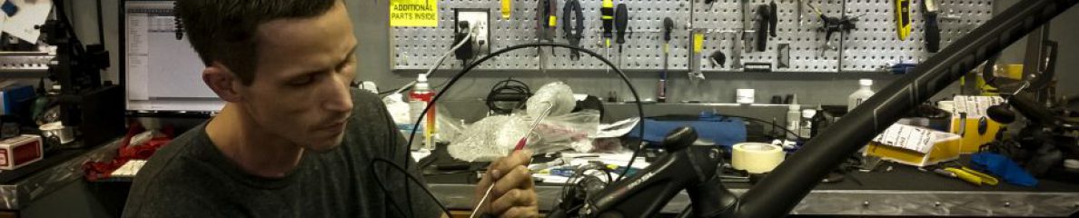
The next part is great.  This is where the skill comes into play.  Before the installation of the new wiring harness, I suggest using an air compressor with a ‘crack pipe’ disc adaptor to clean out the frame of the dust from usage and age.  My buddy, Curtis, photobombed the second photo pretty well and helps me keep focus during these diagnoses.  To loosen the battery pressure plate mounts so you can route the wires, use a long L-hex 5mm to turn them counterclockwise until you can move the plate from the battery compartment with your hand a decent amount.  Note that the frame routing for the rear chainstay motor wires is quite small.  I suggest you route each under the pressure plate and the chainstay separately.   Route each under the pressure plate and then each through the chainstay (check the last photo above for the entrance point).  The wires are pretty stiff and pass through the frame relatively well.  Once you see each (with a nice flashlight), use a pokey tool to route them out of the chainstay. At this point, slide the mesh protector onto the wires and the shrink wrap from the earlier photos.  This will make your life easier in the next few steps. Apply a tiny tiny tiny amount of  dielectric grease to the brass collars of each wire before pushing into the original plastic plug.  This will help seat each wire in the plug a little easier.  It is tough to push them through.  Use a small blunt pokey tool to push from the rear of the plug.  I did it successfully on the second attempt.   Then I I hit the shrink wrap material with a lighter and tightened to the connector and wires.


Once this is done, it’s a matter of connecting everything.  To route the seatpost light wire, I ran a brake wire cable through the tubes and out the seapost drilled hole, taping the connectors in a row to minimize diameter of the hole it had to exit through.

WP_20151015_17_14_23_Pro WP_20151015_17_14_32_Pro WP_20151015_17_14_43_Pro WP_20151015_17_24_46_Pro WP_20151015_17_24_52_ProWP_20151015_15_00_16_Pro WP_20151015_14_53_36_Pro WP_20151015_14_51_59_Pro

Once I had done this, I realized the new harness use d a male and female connector for the rear taillight. Well, I rewired the old connector so it fit, and it worked flawlessly. 🙂

Here is the last of the install photos.

WP_20151015_17_25_01_Pro WP_20151015_17_25_10_Pro WP_20151015_17_25_18_Pro WP_20151015_18_18_27_Pro WP_20151015_18_18_52_Pro WP_20151015_18_19_02_Pro WP_20151015_18_22_37_Pro WP_20151015_18_22_55_Pro

I also realized that the control unit docking station wire was malfunctioning, so I replaced that as well from a known working Turbo S in the shop.  Other than a small few inconsistencies in startup, the firmware was updated successfully as well as the battery communication issue software.  I am still waiting to hear back on the error reports from Specialized.  Bike performs successfully 90% of the time, but a final confirmation from them is necessary.  Thanks for tuning in.  More to come.  I am compiling a great Campagnolo EPS diagnosis article that should be up in the next few days.


SNC, David Polk

Stromer ST1 commute at night with the GoPro Hero4 Silver

Hey everyone!  Finally have my Youtube channel up and running, so I can embed videos now in the blog.  More review on the GoPro Hero4 Silver later, but needless to say, it is one of the coolest gadgets I have ever come across and the possibilities of its usefulness is unlimited.

2015 Turbo and Turbo X Preview / First Thoughts

The 2015 Turbos have arrived! I was psyched on Friday to see the truck roll up with four brand new Turbos and 1 new Turbo X (with a  suspension fork and knobbier tires).  We had been expecting them and I started the builds right away.  I documented the process of unpacking and setting up the bike and the pros and cons of that and exploration of the features as a quick first look.  I am sure we will be seeing them find homes shortly and will continually add summary progress in a troubleshooting article that will build with time.

They were the middle range motor/battery option which seemed to top out at around 21 mph with moderate effort.  Both models feature some great new tech options and builds upon prior years’ success.  They substituted their own branded stem on both models this year instead of the Crank Brothers model from prior years.  The key and battery lock look like a different make and the disc brakes are Formula C1 models.  Much of the rest of the bike is the same.  The Turbo X front light mounts on the handlebar, which I prefer over the Turbo mount at the crown of the fork.  The Rock Shox Paragon 50mm (regular QR) air fork with remote cable lockout is a nice touch on the Turbo X. It is also spec’d with Trigger tires, which I believe might be better suited to substitute Electrak tires.  The first nine photos are of the Turbo X and the rest are of the Turbo and its accessories.  The LCD controller looks the same and mounts in conjunction with the shifter and brake lever.

What I didn’t know about electric bikes

After a lot of research this weekend, I learned quite a bit more about electric bikes and how they work.  I particularly concentrated on how the motor in the rear hub operates and how it can provide power without any moving parts.  My first goal from this point will be to open the hub shell of an Ultra Motor brand hub motor in the rear wheel of a Stromer.  I’ll detail all of it in a well-covered post.

Most of the information I found was on just a couple websites which I somehow had not come across yet. Electric Bike is definitely well organized and provided the most information about a variety of hub motors and their corresponding controllers and diagnostic procedures.  Ypedal has an amazing and vast knowledge of the systems and has created tons of custom setups as well as details repair on several Youtube videos that is a complete procedure and well explained.

Most of the motors have a similar layout:  An outer shell to protect and encase the motor, then a ring of magnets that are positioned between the shell and coils of copper wire.  Other than a couple sensors and wires that exit through the center of the wheel near the axle, that’s about it.  Very simple and once familiar with the parts, moderately easy to work on.  I chose to first learn about the motor because it seems like this is the only component that I haven’t been able to service other than to simply install a replacement wheel.  To have the ability to fix the motors once the manufacturer’s warranty expires will be essential — especially as the number of electric bikes is increasing and they are becoming more common.

Back to the sensors and wires in the motor.  Usually there are three small square shaped sensors that are positioned between two of the outer magnets in line with each other.  These are called Hall sensors and they measure the electrical current coming out of the motor as the wheel spins.  A tapered side of the sensor body is always positioned outward and usually is set with a tiny amount of JB Weld or epoxy. Out of the top of each sensor are three uncovered wire leads that are soldered to colored wires carefully running to the center of the hub and exit from the wheel to the controller and potentially a torque sensor.  A torque sensor is generally on higher end electric bikes while cheaper versions simply use a cadence magnet to calculate the input of added power.  The torque sensor is nicer because it adds power based on a direct measurement of the deflection of the wheel backward against the rear dropout when you put pressure on the chain and pedals.  Most are robust and work accurately, giving the rider a better feel of added power when accelerating.

In some situations, I read that one or more of the Hall sensors can go bad and with the right tools, it is a small project for an afternoon that will avoid a replacement ($500-750) or service elsewhere ($100/hr).  Even if you aren’t up to doing the task yourself, you will be better able to diagnose and familiarize issues that occur.  For the avid mechanic, it is possible to upgrade your hub motor for minimal cost.  Larger wires (if they can fit through the frame and center of the wheel) will boost available power and a better controller or throttle can more accurately distribute the power.  Unless you have an extreme desire to mod your electric bike, the magnets and copper wire are difficult and costly to replace.  Some motors are spun low with larger gauge copper wire which can provide more power, but less torque on hilly terrain while high spin copper will have better power at a high cadence and will last longer.

In order to remove the motor from its hub shell, a car bearing puller is necessary.  It is an extractor style tool with three arms that pull on the shell while a center bolt pushes the axle and opposite hub shell side.  It is helpful and recommended that you tap the shell with a mallet during this process to aid in freeing the two halves.  Otherwise, direct extraction with the bearing puller could break the hub flange and then you’ll be left with a useless motor and no shell.

Considering the Stromer that was detailed in the review and diagnosis, I believe that the torque sensor was overloaded in the frame without that necessary bolt and the motor overheated and fried one or more of the sensors.  This would explain the NO_COMM lack of communication between the LCD controller and the motor.

It makes a lot of sense once the elements are broken down like that.  I also think that one of the wires exiting the rear hub is a faulty wire with a weak spot somewhere near the center of the wheel.  The torque sensor itself seems okay.  I am going to check current through each of the wires to determine the faulty one and then solder in a new one along with the replacement of the sensors.

I was very happy to find this information and come to realization that these bikes can be fixed from the ground up if necessary.  Why wait a week or weeks for new parts to install when the local hardware store and Radio Shack have all the necessary parts for a solution?  I am going to continue to do more research into the motor repairs as well as connecting different controllers to the bike for operation.  It is exciting to realize that with the right research, I can create incredibly fun bikes that are useful for both fun and transportation. Now, once I can locate a car bearing puller, I’ll open the motor and take photos of everything so you can see it.  Stay tuned!

– SNC

Stromer Update Photos and Review Part 2

I have an updated gallery of photos for the Stromer ST1 and will be continuing to review it.  After few more issues and discoveries, I will be posting an article later to detail diagnosing the differences between issues with the display, issues with the motor, and issues with the battery.  Some of the information I have gathered will work to fix the problem and some is for correctly diagnosing what needs a replacement or solution.  In my recent article, I talked about the display having problems and have refined the diagnosis a bit further.  As I compile the information and gather the remaining photos today, browse the gallery and compare the components to what is on your Stromer or other pedelec bicycle.  Once again, I would like to mention that the support from both Specialized and Stromer have been top-notch and most of the models that roll through my shop are trouble free and don’t experience any interruption in use.  It can be overwhelming to read an article that mainly details problems, so I will also try to highlight the good points of design and features that I see.  If you own a Stromer, you probably have spent a bit of time on Google to read forums about issues you may be experiencing and found that the information is loosely organized at best and offers very little in the way of a compiled source other than the company’s website.

The article should be finished up by tomorrow morning.  Enjoy the photos!

Stromer Troubleshooting and Diagnosis Part 1

So, I have done a bit of research in my off time to get more acquainted with the Stromer electric-assist bicycle.  It is the other brand of ebike that we carry in our shop and is notable for its price point and performance.  Not only will it go quite a bit faster than the Turbo (about 50kph or 31mph), but it also comes in at a price point of about $3,500 USD versus the $5,999 tag on the Turbo.  Both equate to an amazing experience on a bicycle, but this option seems more affordable than the Turbo without sacrificing quality.  I like to think of the Turbo as an ebike with style where the Stromer is a workhorse that won’t quit and won’t deteriorate under pressure.

That being said, I wanted to go over a few parts of the Stromer that I have worked with and what expect for a long term review in the future once I ride them a little more.  The Stromer is designed by BMC (the company chose to call itself the initials of its UCI code), a Swiss manufacturer that’s founder was the owner of the famous 711 racing team.  They make two models: the ST1 and the ST2.  Both can be configured with various options from a suspension fork or carbon fiber fork to three levels of motor power and two battery levels.

Stromer ST1 Specs

Stromer ST2 Specs

The ST2 is an upgraded version that has a possible range of 150km on one charge.  That is on of the longest lasting battery specs on the market with 814 Wh.  The newest model has a smartphone integration for real time stats and data.  With built in lights, fenders, and a rear rack, it is a notable competitor for the Turbo S and when the newest model hits our shop, I’ll be posting a review on it.  Until then, I will be dealing with troubleshooting the Stromer ST1 and ST2 from prior years since they are more common.  Having all the information I have gathered in one place will help both you and myself as it expands.  From past research, I have not found very useful information on the Stromer on the Internet and have relied mostly in swapping components from a new build to the repair and having replacements sent from the representative for the company in the USA.  That being said, there is still a great deal of information that can speed up repairs and diagnosis and keep your customers happy and riding.

Much of the issues I have come across seem to deal with replacing the display unit or cleaning connections.  One issue dealt with a bad charger (It should be noted that the charging process of the battery off the bike is very specific).  First, plug the adapter cable to the battery.  Then plug the opposite end of the adapter cable to the charger plug.  Next, plug the power cord into the opposite side of the charger from the adapter cable.  Lastly, plug the power cord into the wall.  You should see a red light appear in the LED bubble on the side of the box charger.  After a few seconds (up to about 5 sec), it should change to either an amber color (signifying it is charging) or green (Stromer recommends leaving the charger on while the LED is green for about an hour for maximum charge level).  If the charging connectors are not plugged together in the correct sequence, damage can occur to the charger and the battery and result in a solid red LED on the charger box.  If this is the case, consult your dealer for a replacement charger.  I have had confusion come from customers on the charging process and it has led me to have to deal with recharging a supposedly malfunctioning battery with a new charger.  In these instances, I also try charging it through the bicycle, which helps to eliminate the battery being the issue.  Here are the photos in order of the process.

Cleaning the connectors should be done carefully and with the battery out of the bike.  While an electrical discharge is not likely, be safe and take the battery out first.  This also provides an opportunity to check the connections for the battery inside the frame and on the battery itself.

Here are a few photos of the various electrical connection on the bike.

The two main issues of display replacement have been related to the information messages shown on the display.  One issue of NO_BATT appeared on the display after only a couple of weeks of use.  I checked the battery both in and out of the frame and the connections leading from the display to the battery.  All of them seemed clean of debris or liquid and were securely connected.  The next step was to reset the display to see if the system would correct itself upon start up.  I removed the display from the handlebars by disconnecting the wires and taking the two anchor screws out of the band mount.  Once removed, I used a quarter to turn the battery cover to the open position underneath the circular gray foam pad protecting it.  Taking a scribe, I popped the cover open and removed the CR2032 battery and inspected the two terminals inside the battery compartment.  Both also seemed clean and correctly positioned for contact.  Taking a new CR2032 battery, I installed it carefully and then put the battery cover and foam pad back.  Mounting it back onto the handlebars, I proceeded to carefully connect all of the wires appropriately and turned the system on.  The message of NO_BATT remained and I contacted the rep about a replacement.  In the short-term, I went ahead and connected a brand new display from a model not yet built to this Stromer and everything seemed to work great afterward.  The replacement unit came in and I reinstalled it onto the new build without issue as well.

Another issue I came across (though I believe it to be from either improper assembly or repair in its past and not from a defect) was a mechanical one.  The spacer nut on the rear axle drive side that correctly positions the freewheel away from the frame was completely missing.  I was able to find a suitable spacer and nut at a local hardware store and the wheel spins freely once again.  As the wheel was initially mounted, the high end of the freewheel was locked against the inside of the rear dropout on the frame and scored a fine line into the metal.  If this had continued, the frame would have likely had to been replaced.  You can see it in the photos here.

I am still not finished with the diagnosis of this particular model.  It has seen quite a few miles of use and also has an issue with the display showing an information message of NO_COMM.  This error means that there is a disruption in the communication between one or more of the components.  I scanned through the connectors, but could find little evidence of a bad wire or connector.  The only connection that seemed to have suffered from the weather was the connection to the rear dropout shown above in the right photo and above on the inside of the chainstay.  I question whether attempted use of the bicycle with the freewheel in its original condition as it came to the shop would have overloaded or shorted the sensor in the frame.  This information has been forwarded to the rep for possible solutions and extra wires to swap and test.  Otherwise, I will attempt to receive a replacement display to test (the models in the shop utilize a 2 wire display, where this model uses a display with 4 wires).  My general feeling is that correction of the rear wheel axle assembly and replacement of the display and rear dropout wire will fix all of the issues.  The bike has had a replacement rear wheel already, so the motor should be in good working order.

I will add to this article as the project progresses!  Feel free to message or comment any questions or suggestions.

– SNC

Specialized Turbo S Long Term Review

Welcome to the long awaited review of the Specialized Turbo S.  The “pedalelec” is an electric pedal assist bicycle for those of you not yet hip on such terminology.  From a newly updated control interface (what you use to configure the Turbo) to a more powerful battery, this bicycle can go about 40 miles at 30 miles an hour.  For locals that know the DC area, that would be like coming into the city from here:

40 miles on 66However, it certainly never takes the quoted 41 minutes by car unless it’s 11:28 pm on a Thursday night (according to googlemaps).  The great news is that you’ll never have to spend all that time sitting in traffic if you’re flying down the taxpayer supported trails of the greater Washington DC metro area or wherever you might live.  It’s a bike that leaves everyone smiling the first time they use one and was designed for commuting and recreation by some of Europe’s best bicycle experts with Specialized.  Every single person I have ever seen test ride or own one is smiling ear to ear afterward.

Group ride bikes lined up in three sizes, S, M, L

This review intends to convey the nature of the bicycle and how it operates as well as issues encountered from a maintenance standpoint over a long period of usage.  I would be the first to admit that, amongst a few expected difficulties, it is a machine worth the investment and is a forefront in the future of this class of bicycles.

Building a Turbo out of the box is not altogether difficult and can be done by most shops with some attention to detail and a thorough reading of the manual.  You might recall from my original article that I attended a seminar on how to operate and work on the Specialized Turbo in Miami back in 2013 and it definitely helped to have time properly set aside to fully understand how it works and how to replace components and fix others in the past few months of research.  With a final recent repair of the regeneration mode activated hydraulic disc brakes by Magura, I felt there was sufficient photos and information to write a good “one-stop” informal manual in case you run into a similar situation.  As started, the build includes normal things like truing the wheels which are installed on the bike with thru-axles and have torque specs located right at each point on the frame and fork.  These specs are important as this bicycle will undergo higher stresses than a majority of other bicycles at higher speed.

So, all of this being said, i think that it’s clear how cool and fun these bikes are to work with and enjoy.  There are certain maintenance issues that seemed to take a fair amount of time to work out, but most of the solutions made great sense after diagnosing and repairing.  I would like to begin by saying this quick procedure, found in the manual, solves many small issues:

1.  Power off the Turbo by lightly clicking the green lit button on the battery.

2.  Turn the key included with the bike down near the bottom bracket and hold.

3.  Lift the battery out from the downtube.

4.  Wait about thirty seconds.

5.  Place the battery (bottom first) and reinstall.

6.  Turn on the Turbo.

Essentially, taking the battery (powered down) out of the Turbo resets the entire system much like unplugging your Internet router at home or work and powering it back on after a few moments.  Every time it starts up, the Turbo passes through a set of diagnostic checks that relay to four small LEDs located right below the power button on the battery.  Each LED should blink once and then remain on until all four have lit up.  Then, all four LEDs should blink together once and then resolves into a battery level meter (each LED represents 25% battery).  If the LEDs have lit up as mentioned, the system has just checked the battery status, the motor status, the control interface status, and the lighting system status.  On the current Turbo S (versus the original model), there is a front light as well as a new integrated rear set of LEDs on the back of the saddle (nice addition).

Turbo Battery

However, at times throughout the research, I would notice one or two LEDs blink twice when the Turbo was turned on and so I checked the manual and diagnostic chart from the Specialized Service website.  Any of the four LEDs blinking twice indicates that there is some sort of fault or error with the corresponding module (battery, motor, CPU, or lights).  The lights and control interface (we’ll call it the CPU) are wired in parallel and it should be mentioned that a fault (LED blinks twice) from either might mean checking both for error.  This has happened on several occasions and could always be resolved, but a check of both modules was usually necessary.  The number one thing I found helpful to do in the case of an error was to immediately check all of the wire connections on the bike to make sure they were properly tight and paired.  In some cases, I found it helpful to use a very small amount of dielectric grease to ensure that the connection was consistent.

From all of the repairs, I have installed or replaced the following: the battery (both the same unit and upgrading the original Turbo with a new unit), bottom bracket (BB386EVO), rear derailleur (SRAM X0), hydraulic brakes (Magura), and the CPU (both updating firmware and software and installing a new unit).  One thing I have never had to replace (on a Turbo) is a spoke.  The wheels were designed and built extremely well and the Specialized Electrak tires are perfect for the bike.  Many other electric bikes I have serviced have experienced spoke breakage and warping of the rim.  As a part of the bike that most people cannot repair on the road without training and tools, it’s a great confidence to know they hold up so well, even with daily commuting, running errands, and several crashes.

I am going to add links below for each section of the review (two additional parts) for ease of navigation.  Once the link is active, the post for the corresponding link will be up.  This way, it’s easier to jump to a section if you are servicing a Turbo and can read the most relevant information.

Parts Installation (Active)

Diagnosis and Troubleshooting (Active)

Wheel Truing and Specialized Turbo Long Term Review

I will be posting a short article tomorrow evening on wheel truing and will also post Part 1 of all the info and tuning/adjustments I have been through and discovered with the Specialized Turbo S Pedelec bike. I look forward to your thoughts!  Stay tuned for for great info and photos.

P.S.  I also edited the Dura-Ace 9000 front derailleur setup article after reviewing a few comments from readers and my own experiences with the setup.


Image

Image

Image

– SNC