Welcome to Part 2 of 3 in my Specialized Turbo S Long Term Review. I feel like this is some of the most essential information that I can apply in one place that will keep Turbo pedalelecs running beautifully. However, I do feel that there is a “low-ceiling” limit to the depth that the Turbo can be maintained — even by an experienced and well-equipped shop. In certain instances, the bike may have to be sent to the factory. I am of the belief that this is being addressed and the bike will become even more modular and accessible. That being said, there is a ton that will be covered here and includes several years of work and knowledge. While I will be mostly highlighting troubled issues, the Turbo overall has been very trouble free and generally without issue. This just compiles issues from many Turbos I have serviced since their release.
Onward.
So, I turned on my Turbo and started pedaling and the motor did not kick in as expected in Full Active and Eco modes. What’s up with that?
I am starting with this problem because I think it has occurred more than any other issue. There are a number of symptoms that cause it to happen and a number of solutions. First, the battery is nearly dead. Charge it up and try again. The next thing I would try is to simply turn it off and turn it on again to try it. This occurrence has spanned several Turbo S bikes on a rare occasion and has been remedied every time in the shop. The next reason it might not turn on is that the battery may not have been installed properly or the pressure plate at the bottom of the battery “hanger” is not correctly adjusted.
With the battery pressure plate, I have found it to be different on each bike and definitely has a “correct” pressure for the Turbo to function right. On the bottom of the bike behind the bottom bracket is an access plate that is secured by small 2mm bolts. Remove these and set aside in a magnetic parts tray so they don’t end up lost on the ground. Once the anchor plate has been removed, look inside and you’ll see wires, a couple hex bolts, and the shell of the bottom bracket. Locate the 5mm hex bolt right in the center anchored into a flat plate. This is an adjustment bolt for moving the battery up and down within the battery dock. It provides pressure against the battery so vibrations do not disrupt the connection at the opposite end of the down tube. To be noted, one would likely expect the phrase, “Why not just crank that thing down and really lock it in there?” Well, here’s why. If the motor does not seem to be engaging as aforementioned, this same issue can occur if the battery is adjusted to tightly in the dock. Just as the battery has a little “wiggle” room, so does the connection to the battery inside the frame at the top tube and head tube junction. If you remove the battery and look at the top of the battery dock, you’ll see where it plugs in. With your fingers or a scribe, you can definitely see gaskets on the side of the connection and its ability to move slightly up, down, left, or right with a small amount of push. The general rule is to begin tightening the pressure plate while using your free hand to try and move the battery up and down in the frame. If you hear any sharp noises when it contacts the top or bottom, continue tightening. Once there is little movement (0.25-0.5mm), stop tightening and use the key to remove the battery. If it is too tight, it will be difficult to get the battery out. I have found that each Turbo is slightly different, which is a great reason to have the plate for adjustment.
Another item to check is the connections between the brake and the control unit and the connection to the wire coming out of the frame. Also, as a measure of being thorough, there is an additional connection inside the frame at the head tube where the light plugs into a parallel connector with the control unit (Several times, fault signals on the battery will indicate the light and control unit both having an issue when it is mostly one or the other). By checking these connections, I imply: Are they tight and correctly aligned for the individual connector pins? Have you applied a tiny amount of dielectric grease to the threads of the connectors? Are the connections and wires constantly rattling or loose? Try checking each of these regularly when servicing as a quick way of eliminating them in the event of an issue.
So, I turned on my Turbo and everything started up, but a flashing code reading “short circuit” is displaying on the control unit? Is that bad?
Well, it’s not necessarily good, but can be fixed easily. Sometimes, constant vibration, continued exposure to the elements, and leaving the rubber charging cap off of the Turbo for extended amounts of time can cause an interruption in the electrical system and send a red flag to the control unit. It’s a feature designed to override the system much like a circuit breaker so no damage occurs to vital components. By using the Turbo diagnostic tool plugged into the frame (with battery in) and into a laptop, you can run the diagnostic software and release the hold on the circuit with a convenient button on the screen. This software is a very important tool in confirming that the motor, battery, control unit, and lights are working properly and displays a wealth of information and reports for keeping Turbos happy and healthy.
My Turbo has gone insane and decided to run at 28mph like a throttle as soon as I hit the pedal. I don’t even need to pedal. Glad it’s spec’d with great disc brakes. Does it need an exorcism?
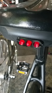
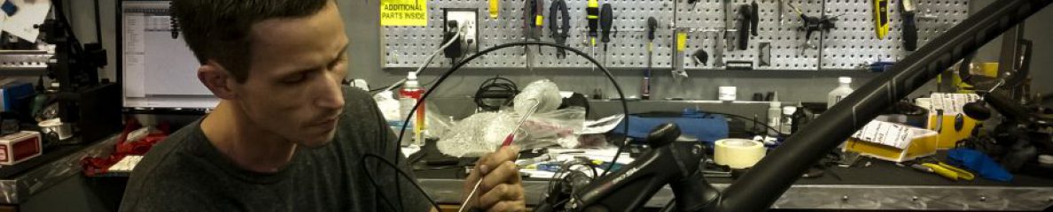
Not quite. In the early days, Specialized might have taken this approach, but with the “Innovate or Die” theme currently in trend, we now know it’s quite real. This issue has only occurred once, yet is important enough to catalog and solve for any future happenings. In my prior post, I detailed the symptoms of the bike while it was secured in the bike stand. I took the opportunity to remove and clean some of the components on the bike and the frame (After slowly and carefully removing the kickstand, I have realized that unless it is absolutely necessary, don’t ever remove it. It is tedious because of the frame angles to loosen and tighten the 8mm hex bolt and I found that it didn’t improve access to the electronics and pressure plate under the bottom bracket. It is a very sturdy dual kickstand that stays tight and balances great.). That being said, I removed the bottom bracket (EVO386) with a socket and outboard cup adaptor and found plenty of access points into the frame to see the wires running to the motor and seatpost LED and the hex bolt adjustment for the pressure plate (5mm) and the lock mechanism with it’s integration into the battery release. I wiped the battery dock and the battery with isopropyl alcohol. The terminal connections were also cleaned with isopropyl and a swab. With some time open in the service schedule, I also decided to remove the external frame charger / battery dock connection unit from the top end of the down tube to make sure all of the connections looked secure and free of debris and moisture. Thanks to a well-sealed compartment, everything looked great. I took notes as well on the direction, colors, and pairing of wires that interfaced with the unit. Red and black paired wires run directly from this to the bottom bracket shell, under the EVO386 BB, and through the non-drive chainstay to the external port near the rear wheel. A shorter set of these two wires also connects the battery dock connection to the external charge port. Two sets of blue and brown wires run from the unit to the headtube and into the brake / control interface and also to the bottom bracket shell and into the seat tube to connect into the wires running from the saddle’s integrated LED through the seatpost. One triple set of wires (blue/brown/green) run from the external charge port in the frame to the top of the battery dock where the battery connects to the system. Lastly, an orange wire runs from the front light to the connection with the control interface (wired in parallel). As a side note, this is why the diagnostic on the battery will show both the light and control interface having an issue when it could potentially only be one of them. Good things lights are pretty easy to check.
Once I had satisfied my curiosity of understanding the Turbo S better, I moved on to reinstalling the parts and activating the wheel like before. I let it run continually for over five minutes with no discernible change. Continuous operation, only to be paused by giving the brake a solid squeeze. If the wheel was touched, the throttle would pick up again. This was also true for pressure on the pedals. In these situations, I was lucky to have another in the store to help eliminate components. Taking a brand new rear wheel from the second Turbo (after testing to make sure it was operational), I installed it into the first and powered the system. No activation of Full Active or Eco modes, but No Power worked as expected and Regen mode seemed more difficult than normal as mentioned with the original wheel. This is the only area that I am not quite sure what to think of yet. That’s what the techs at Specialized are for. Continuing with the diagnosis, I also swapped the battery with no effect. Reinstalling the original wheels and batteries to each Turbo, I then swapped the control interfaces. This also did not yield any effect. With the original wheel, the throttle accelerated as before (One thing I might try today is to try both battery, control interface, and new rear wheel from the second Turbo into the first.). The last thing I did was to put the wheel from the service Turbo into the new Turbo. It accelerated to 28mph. Thus, my conclusion (though I will wait for confirmation from Specialized) is that the wheel needs to be recalibrated–specifically the motor. If this is the case, it will go back to the factory for a quick turnaround and then I’ll have an update on a future post about the issue’s resolution. This was a great opportunity to fully inspect the bike from top to bottom, inside and out.
I am going to continue this post through the weekend with some other minor issues and fixes that will keep the Turbo S running smooth and fast, but figured that it’d be good to start posting the article for any feedback or questions.
Here are photos of the above parts:


More to follow! – SNC